In this webpage you find 2 Java Applets at the bottom
that simulate turning a Paraglider in Thermal to get the best lift.
The Java based package can be accessed from http://sourceforge.net/projects/t3d2 or from http://t3d2.sourceforge.net/ or from here .
If the Applets do not work then you are missing a Java 1.4 Runtime environment.
The wing data is xml based
.
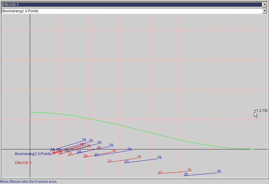
Here are some screen shots from the applet.

I am comparing an Effect 38 with a Boomerang 2.
Effect is red, Boomerang is blue.
In a 3m/s max peak thermal with a 80 m radius , the Effect can thermal
slightly tighter and can therefore climb better.
The numbers on the tips of the lines correspond to the speed at the
wing tips. The length of the line is roughly the projected wing span.
The inclination of the line indicates the bank angle.
The thermal strength is 10 times exaggerated compared to the radius.
Only the best toggle combination to obtain a certain radius gets displayed.
There are many more combinations of toggle settings, but they all result
in a worse climb of the glider.

In a 2 m/s max thermal with a 40m radius an Effect can just make it.

If it is a very small but strong thermal then the Effect got a big advantage.
But in a weak and wide thermal the Boomerang 2 got an advantage in the thermal and will get away.

In a nutshell, a lower performace glider can outthermal a high performance
glider in certain thermal conditions.
By making use of the lower stall and trim speed one can reduce
the radius and get more into the core with the stronger lift.
This jJava applet tries to compare and simulate two paragliders turning
in a thermal.
The 2 figures at the end of each line indicate the speed of the wing
tips.
How much toggle is applied.
And the code tries to find the best speed combination to make optimal
use of the thermal
The Java Applet should be below this line.
If not then you might need the JAVA runtime environment. Or a JAVA enabled Web Browser.
Using a different thermal crossection, more punchy, dust devil type like....
Some background info
The thermal is a math degree 3 parabola .
The turn radius of the glider is determined by the 2 toggle speeds for the inner and outer wing.
vi , inner wing speed
vo, outer wing speed
speeds can go from stallspeed to trim speed
projected wing span is s
turn radius is r
inner speed vi is at radius - (s / 2)
outer speed vo is at radius + (s /2)
center speed v = ( vi + vo ) /2
vi / (r-s/2) = vo / (r+s/2)
vo*r - vo*s/2 = vi*r + vi*s/2
r*(vo-vi) = (vi+vo)*s/2
radius r = (s/2) * (vi+vo) / (vo-vi)
The centrifugal acceleratione while turning is
z = v*v / r
while the usual weight stays pointing down with g = 9.81 m/ss
You bank angle is tan a = z/g
The sink of the glider is determined by using the center speed
v
and applying it on the polar definition of the glider.
But this sink would apply for straight and level flight.
The adjusted sink = sink / cos a , with a the bank angle
The total lift or sink of the glider in the thermal is then defined as
total = lift by thermal + adjusted sink
with lift by thermal a positibe value
and adjusted sink a negative value in m/s
The code iterates through vi and vo from stall speed to trim speed
The polar is defined from minimum sink to maximum speed
Which is not 100 percent correct for this approach here.
The part of the polar from stall speed to minimum sink is missing.
If the center speed is below minimum sink speed I set
it to minimum sink.
Download the best jar file
One can use zip or jar to unzip the best.jar file.
Then modify the wingdata.xml file and add your glider data to it.
The wingdata.xml file format
PolarCount can be 3 or 4 or 5 for the amount of polare points
The first point has to be the minimum sink point. Where the polare tangent is horizontal.
The next points have to points on the polare as the speed increases.
The last point is the top speed on the polare.
A point is defined by the speed in km/h and a sinkvalue im m/s
Java 1.4 has to be installed
To run the code on your computer, get the best.jar file .
In a Command Window, jar -xvf best.jar
And use java appletcode/Best/BestTurnApplet_1.class to bring up the code on your computer.
Polar data info you find at
http://www.para2000.org/wings/index.html
The code has also been integrated with T3D2
http://sourceforge.net/projects/t3d2
http://t3d2.sourceforge.net/